ZZC
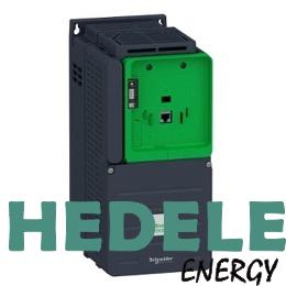
ATV930U75N4Z Process ATV900, ATV930, 7,5 kW,
Schneider Variable speed drive, Altivar 380...480 V, cabinet Integration, IP20
Discrete input logic
16 preset speeds
Asynchronous motor control profile
Variable torque standard
Constant torque standard
Optimized torque mode
Synchronous motor control profile
Permanent magnet motor
Synchronous reluctance motor
Maximum output frequency
599 Hz
switching frequency
2...16 kHz adjustable
4...16 kHz with derating factor
Nominal switching frequency
4 kHz
line current
13.8 A at 380 V (normal duty)
10.5 A at 380 V (heavy duty)
11.9 A at 480 V (normal duty)
9.2 A at 480 V (heavy duty)
apparent power
9.9 kVA at 480 V (normal duty)
7.6 kVA at 480 V (heavy duty)
maximum transient current
19.8 A during 60 s (normal duty)
19.1 A during 60 s (heavy duty)
Network frequency
50...60 Hz
Prospective line Isc
50 kA
Discrete input number
10
discrete input type
DI1...DI8 programmable, 24 V DC (<= 30 V), impedance: 3.5 kOhm
DI7, DI8 programmable as pulse input: 0…30 kHz, 24 V DC (<= 30 V)
STOA, STOB safe torque off, 24 V DC (<= 30 V), impedance: > 2.2 kOhm
Discrete output number
2
discrete output type
Logic output DQ+ 0…1 kHz <= 30 V DC 100 mA
Programmable as pulse output DQ+ 0…30 kHz <= 30 V DC 20 mA
Logic output DQ- 0…1 kHz <= 30 V DC 100 mA
Analogue input number
3
analogue input type
AI1, AI2, AI3 software-configurable voltage: 0...10 V DC, impedance: 30 kOhm, resolution 12 bits
AI1, AI2, AI3 software-configurable current: 0...20 mA/4...20 mA, impedance: 250 Ohm, resolution 12 bits
Analogue output number
2
analogue output type
Software-configurable voltage AQ1, AQ2: 0...10 V DC impedance 470 Ohm, resolution 10 bits
Software-configurable current AQ1, AQ2: 0...20 mA impedance 500 Ohm, resolution 10 bits
Relay output number
3
relay output type
Configurable relay logic R1: fault relay NO/NC electrical durability 100000 cycles
Configurable relay logic R2: sequence relay NO electrical durability 1000000 cycles
Configurable relay logic R3: sequence relay NO electrical durability 1000000 cycles
maximum switching current
Relay output R1 on resistive load, cos phi = 1: 3 A at 250 V AC
Relay output R1 on resistive load, cos phi = 1: 3 A at 30 V DC
Relay output R1 on inductive load, cos phi = 0.4 and L/R = 7 ms: 2 A at 250 V AC
Relay output R1 on inductive load, cos phi = 0.4 and L/R = 7 ms: 2 A at 30 V DC
Relay output R2, R3 on resistive load, cos phi = 1: 5 A at 250 V AC
Relay output R2, R3 on resistive load, cos phi = 1: 5 A at 30 V DC
Relay output R2, R3 on inductive load, cos phi = 0.4 and L/R = 7 ms: 2 A at 250 V AC
Relay output R2, R3 on inductive load, cos phi = 0.4 and L/R = 7 ms: 2 A at 30 V DC
minimum switching current
Relay output R1, R2, R3: 5 mA at 24 V DC
Physical interface
Ethernet
2-wire RS 485
connector type
2 RJ45
1 RJ45
method of access
Slave Modbus TCP
Transmission rate
10, 100 Mbits
4.8 kbps
9600 bit/s
19200 bit/s
Transmission frame
RTU
Number of addresses
1…247
Data format
8 bits, configurable odd, even or no parity
Type of polarization
No impedance
4 quadrant operation possible
True
Acceleration and deceleration ramps
Linear adjustable separately from 0.01...9999 s
Motor slip compensation
Can be suppressed
Adjustable
Not available in permanent magnet motor law
Automatic whatever the load
Braking to standstill
By DC injection
Brake chopper integrated
True
Maximum input current
13.8 A
Maximum output voltage
480.0 V
Relative symmetric network frequency tolerance
5 %
Base load current at high overload
12.7 A
Base load current at low overload
16.5 A